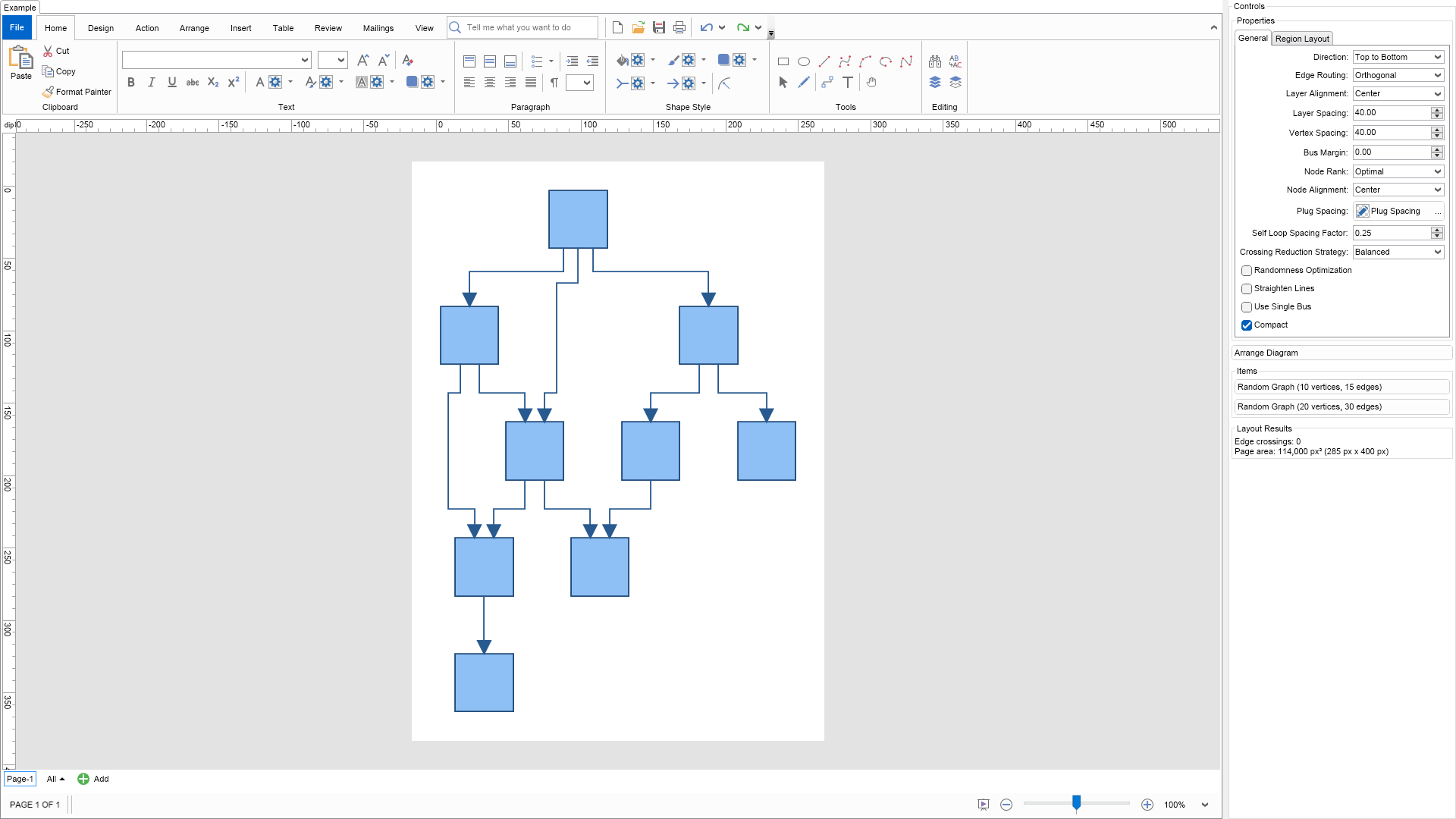
Nevron NOV Diagram for Blazor ships with hundreds of examples with full source code, as part of the Nevron Open Vision Suite.
All Blazor Diagram examples are also available as a stand-alone Visual Studio solution
in C#,
which you can download from the links below.
Layered Graph Layout Example for Blazor Description
The layered graph layout is used to layout a graph in layers.
The layout strives to minimize the number of crossings between edges
and produces a polyline graph drawing. This type of layout is very useful
for the arrangement of flow diagrams, since it works well on all types of graphs
(including those with self-loops and duplicate edges).
The most important properties are:
Direction - determines the flow direction of the layout. By default set to TopToBottom.
EdgeRouting - determines what edge routing is applied. Possible values are:
Polyline - the edges are drawn using a polyline with few bends
Orthogonal - the edges are drawn using only horizontal and vertical line segments
NodeRank - specifies the node ranking policy used by the layout. It can be:
TopMost - all nodes without incoming edges are assigned to the topmost layer
Gravity - layer distribution is done in such a way that the total length of all edges is minimized
Optimal - similar to the topmost, but after the initial assignment all nodes fall downwards as much as possible
PlugSpacing - determines the spacing between the plugs of a node.
You can set a fixed amount of spacing or a proportional spacing, which means that the plugs
are distributed along the whole side of the node.
LayerAlignment - determines the vertical alignment of the nodes in the layers.
NodeAlignment - determines the horizontal alignment of the nodes in the layers.
SelfLoopSpacingFactor - determines the self-loop spacing factor. It spaces the self-loops as a ratio of the body height.
VertexSpacing and LayerSpacing - determine the spacing between nodes and layers
respectively.
StraightenLines - if turned on an additional step is performed that tries to
straighten the lines as much as possible in the case of orthogonal edge routing.
UseSingleBus - if true and the EdgeRouting is orthogonal, all edges will be
placed on a single bus between each pair of layers.
Compact - determines whether the layout should try to minimize the width of the drawing or not.
You can set the index of a given node in its layer explicitly using the IndexInLayer property
from the LayoutData collection of the node. By default the index is set to -1 which
means that the layout will automatically calculate it. If you set a value greater than or equal
to 0 the node will be placed at that index. If the index is greater than the total number
of nodes in the layer, it will be set equal to the number of vertices - 1.
To experiment with the layout just change its properties from the property grid and click the Layout button.
To see the layout in action on a different graph, just click the Random Graph button.
C# Layered Graph Layout Example Code for Nevron Diagram for Blazor
Language: C#
using Nevron.Nov;
using Nevron.Nov.DataStructures;
using Nevron.Nov.Diagram;
using Nevron.Nov.Diagram.Layout;
using Nevron.Nov.Diagram.Shapes;
using Nevron.Nov.Dom;
using Nevron.Nov.Editors;
using Nevron.Nov.Graphics;
using Nevron.Nov.Layout;
using Nevron.Nov.UI;
using Nevron.Nov.Windows.Forms;
using System;
using System.Windows.Forms;
namespace NovWinFormsProject
{
public partial class Form1 : Form
{
#region Constructors
public Form1()
{
InitializeComponent();
// Set form title
Text = "NOV WinForms - NLayeredGraphLayoutExample";
// Create the NOV example and its controls
NWidget exampleContent = CreateExampleContent();
NWidget exampleControls = CreateExampleControls();
if (exampleControls != null)
{
exampleControls.PreferredWidth = 300;
}
// Place the example and its controls in a pair box
NPairBox pairBox = new NPairBox(exampleContent, exampleControls);
pairBox.FillMode = ENStackFillMode.First;
pairBox.FitMode = ENStackFitMode.First;
pairBox.Margins = new NMargins(NDesign.HorizontalSpacing, NDesign.VerticalSpacing);
// Host the example in the form
NNovWidgetHost host = new NNovWidgetHost(pairBox);
host.Dock = DockStyle.Fill;
Controls.Add(host);
}
#endregion
#region Example
public NWidget CreateExampleContent()
{
// Create a simple drawing
NDrawingViewWithRibbon drawingViewWithRibbon = new NDrawingViewWithRibbon();
m_DrawingView = drawingViewWithRibbon.View;
m_DrawingView.Document.HistoryService.Pause();
try
{
InitDiagram(m_DrawingView.Document);
}
finally
{
m_DrawingView.Document.HistoryService.Resume();
}
return drawingViewWithRibbon;
}
public NWidget CreateExampleControls()
{
m_Layout.Changed += OnLayoutChanged;
NStackPanel stack = new NStackPanel();
// property editor
NEditor editor = NDesigner.GetDesigner(m_Layout).CreateStandaloneEditor(m_Layout);
stack.Add(new NGroupBox("Properties", editor));
NButton arrangeButton = new NButton("Arrange Diagram");
arrangeButton.Click += OnArrangeButtonClick;
stack.Add(arrangeButton);
// items stack
NStackPanel itemsStack = new NStackPanel();
// NOTE: For Graph layouts we provide the user with the ability to generate random graph diagrams so that he/she can test the layouts
NButton randomGraph1Button = new NButton("Random Graph (10 vertices, 15 edges)");
randomGraph1Button.Click += OnRandomGraph1ButtonClick;
itemsStack.Add(randomGraph1Button);
NButton randomGraph2Button = new NButton("Random Graph (20 vertices, 30 edges)");
randomGraph2Button.Click += OnRandomGraph2ButtonClick;
itemsStack.Add(randomGraph2Button);
stack.Add(new NGroupBox("Items", itemsStack));
// Create the layout result label
m_ResultLabel = new NLabel();
stack.Add(new NGroupBox("Layout Results", m_ResultLabel));
UpdateResultLabel();
return stack;
}
public string GetExampleDescription()
{
return @"
The layered graph layout is used to layout a graph in layers.
The layout strives to minimize the number of crossings between edges
and produces a polyline graph drawing. This type of layout is very useful
for the arrangement of flow diagrams, since it works well on all types of graphs
(including those with self-loops and duplicate edges).
The most important properties are:
Direction - determines the flow direction of the layout. By default set to TopToBottom.
EdgeRouting - determines what edge routing is applied. Possible values are:
Polyline - the edges are drawn using a polyline with few bends
Orthogonal - the edges are drawn using only horizontal and vertical line segments
NodeRank - specifies the node ranking policy used by the layout. It can be:
TopMost - all nodes without incoming edges are assigned to the topmost layer
Gravity - layer distribution is done in such a way that the total length of all edges is minimized
Optimal - similar to the topmost, but after the initial assignment all nodes fall downwards as much as possible
PlugSpacing - determines the spacing between the plugs of a node.
You can set a fixed amount of spacing or a proportional spacing, which means that the plugs
are distributed along the whole side of the node.
LayerAlignment - determines the vertical alignment of the nodes in the layers.
NodeAlignment - determines the horizontal alignment of the nodes in the layers.
SelfLoopSpacingFactor - determines the self-loop spacing factor. It spaces the self-loops as a ratio of the body height.
VertexSpacing and LayerSpacing - determine the spacing between nodes and layers
respectively.
StraightenLines - if turned on an additional step is performed that tries to
straighten the lines as much as possible in the case of orthogonal edge routing.
UseSingleBus - if true and the EdgeRouting is orthogonal, all edges will be
placed on a single bus between each pair of layers.
Compact - determines whether the layout should try to minimize the width of the drawing or not.
You can set the index of a given node in its layer explicitly using the IndexInLayer property
from the LayoutData collection of the node. By default the index is set to -1 which
means that the layout will automatically calculate it. If you set a value greater than or equal
to 0 the node will be placed at that index. If the index is greater than the total number
of nodes in the layer, it will be set equal to the number of vertices - 1.
To experiment with the layout just change its properties from the property grid and click the Layout button.
To see the layout in action on a different graph, just click the Random Graph button.
";
}
///
/// Gets the relevant documentation links for the example
///
///
public (string Name, string Url)[] GetDocumentationUrls()
{
return new[]
{
("Layered Graph Layout", "https://www.nevron.com/docs/openvision/diagram-layered-graph-layout.html"),
("Layouts Overview", "https://www.nevron.com/docs/openvision/diagram-drawing-layouts-overview.html"),
("Graph Regions and Regions Layouts", "https://www.nevron.com/docs/openvision/diagram-graph-regions-and-region-layouts.html"),
("Shape Navigation", "https://www.nevron.com/docs/openvision/diagram-shape-navigation.html"),
};
}
private void InitDiagram(NDrawingDocument drawingDocument)
{
const double width = 40;
const double height = 40;
const double distance = 80;
// Hide ports
drawingDocument.Content.ScreenVisibility.ShowPorts = false;
NBasicShapeFactory basicShapes = new NBasicShapeFactory();
NPage activePage = drawingDocument.Content.ActivePage;
int[] from = new int[] { 1, 1, 1, 2, 2, 3, 3, 4, 4, 5, 6 };
int[] to = new int[] { 2, 3, 4, 4, 5, 6, 7, 5, 9, 8, 9 };
NShape[] shapes = new NShape[9];
int vertexCount = shapes.Length, edgeCount = from.Length;
int i, j, count = vertexCount + edgeCount;
for (i = 0; i < count; i++)
{
if (i < vertexCount)
{
j = vertexCount % 2 == 0 ? i : i + 1;
shapes[i] = basicShapes.CreateShape(ENBasicShape.Rectangle);
if (vertexCount % 2 != 0 && i == 0)
{
shapes[i].SetBounds(new NRectangle(
(width + (distance * 1.5)) / 2,
distance + (j / 2) * (distance * 1.5),
width,
height));
}
else
{
shapes[i].SetBounds(new NRectangle(
width / 2 + (j % 2) * (distance * 1.5),
height + (j / 2) * (distance * 1.5),
width,
height));
}
activePage.Items.Add(shapes[i]);
}
else
{
NRoutableConnector edge = new NRoutableConnector();
edge.UserClass = NDR.StyleSheetNameConnectors;
activePage.Items.Add(edge);
edge.GlueBeginToShape(shapes[from[i - vertexCount] - 1]);
edge.GlueEndToShape(shapes[to[i - vertexCount] - 1]);
}
}
// arrange diagram
ArrangeDiagram(drawingDocument);
// fit active page
drawingDocument.Content.ActivePage.ZoomMode = ENZoomMode.Fit;
}
#endregion
#region Implementation
///
/// Arranges the shapes in the active page.
///
///
private void ArrangeDiagram(NDrawingDocument drawingDocument)
{
// get all top-level shapes that reside in the active page
NPage activePage = drawingDocument.Content.ActivePage;
NList shapes = activePage.GetShapes(false);
// create a layout context and use it to arrange the shapes using the current layout
NDrawingLayoutContext layoutContext = new NDrawingLayoutContext(drawingDocument, activePage);
m_Layout.Arrange(shapes.CastAll
Download a fully functional C# (.cs) Layered Graph Layout Example for Blazor Solution

 Chart for .NET
 Diagram for .NET
 User Interface for .NET
 Vision for SSRS
 Chart for SSRS
 Gauge for SSRS
 Map for SSRS
 Barcode for SSRS
 Vision for SharePoint
 Chart for SharePoint
 Gauge for SharePoint
 Map for SharePoint
 Barcode for SharePoint
 Open Vision for .NET


 Vision for .NET